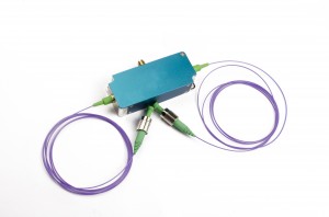
Low-power N-type Acousto Optic Driver for 532nm Fiber AOM Series
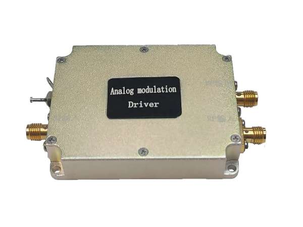
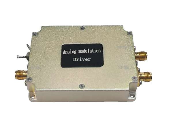
An acousto-optic driver is an RF driver designed to offer support for acousto-optic device products. It is suitable for driving acousto-optic modulators and frequency shifters with a power requirement of less than 3W. The RF signal produced by the driver is utilized to generate ultrasonic waves in the crystal of the acousto-optic device. The modulation, deflection, or tuning of the beam is influenced by the frequency and intensity of the applied RF signal. The driver features efficient heat dissipation, and employing a matched drive enhances temperature stability.
| Supporting Drive | The model (SGXXXX-33-N-ab) employs “X” to denote the frequency shift function, “Y” for the modulation function, and “T” for the modulation function. The “XXX” signifies the operating frequency, where “33” corresponds to the RF output power. “N” indicates the package type. The letter “A” is used with “1” representing a power supply voltage of 24V and “2” for a power supply voltage of 12V. The letter “b” is designated for modulation type, with “D” indicating digital TTL modulation and “A” representing analog modulation. | ||
| SGT100-33-N-1D | SGT150-33-N-1D | SGT250-33-N-1D | |
| SGT100-33-N-1A1 | SGT150-33-N-1A1 | SGT250-33-N-1A1 | |
| SGT100-33-N-1A5 | SGT150-33-N-1A5 | SGT250-33-N-1A5 | |
Performance of Low-power N-type Acousto Optic Driver on Fiber AOM
- Small size
- Fast response time
- Low power consumption
- High-temperature stability and reliability
|
parameter |
Unit |
SGT100-33-N-1A |
SGT80-33-N-2D |
SGT200-32-N-1D-1 |
|
|
Specifications of the modulation input interface |
|||||
|
Modulated signal input |
- |
Analog modulation 0-1V |
Digital modulation(high level3.3-5V; low level 0-0.2V@1kΩ) |
||
|
Modulated signal input impedance |
Ω |
50 |
1k |
1k |
|
|
Interface |
- |
SMA |
|||
| RF output interface specification | |||||
|
Output signal frequency |
MHz |
100 |
80 |
200 |
|
|
Frequency stability |
ppm |
100 |
100 |
1 |
|
|
Output signal power |
W |
2.0 |
2.0 |
1.6 |
|
|
Rise and fall time |
ns |
<20 |
<20 |
<8 |
|
|
Switching ratio |
dB |
≥60 |
|||
|
Harmonic suppression ratio |
dBc |
>25 |
|||
|
Signal output standing wave ratio |
- |
≤1.3 |
|||
|
Interface |
- |
SMA |
|||
|
Complete Machine Specification |
|||||
|
Maximum power consumption |
W |
10 |
10 |
10 |
|
|
Working voltage |
Vdc |
24±1V |
12±0.5V |
24±1V |
|
|
Power interface |
- |
Through core capacitance (core wire is connected to positive, solder lug is connected to negative) |
|||
| Note: Interfaces without specification are non-functional terminals, please ignore. | |||||
Package Specification:
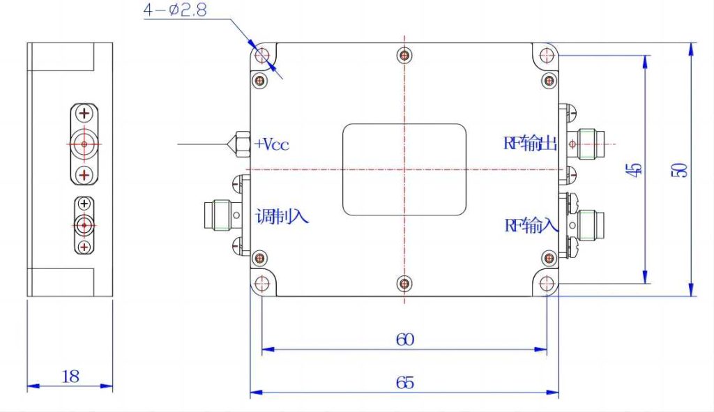
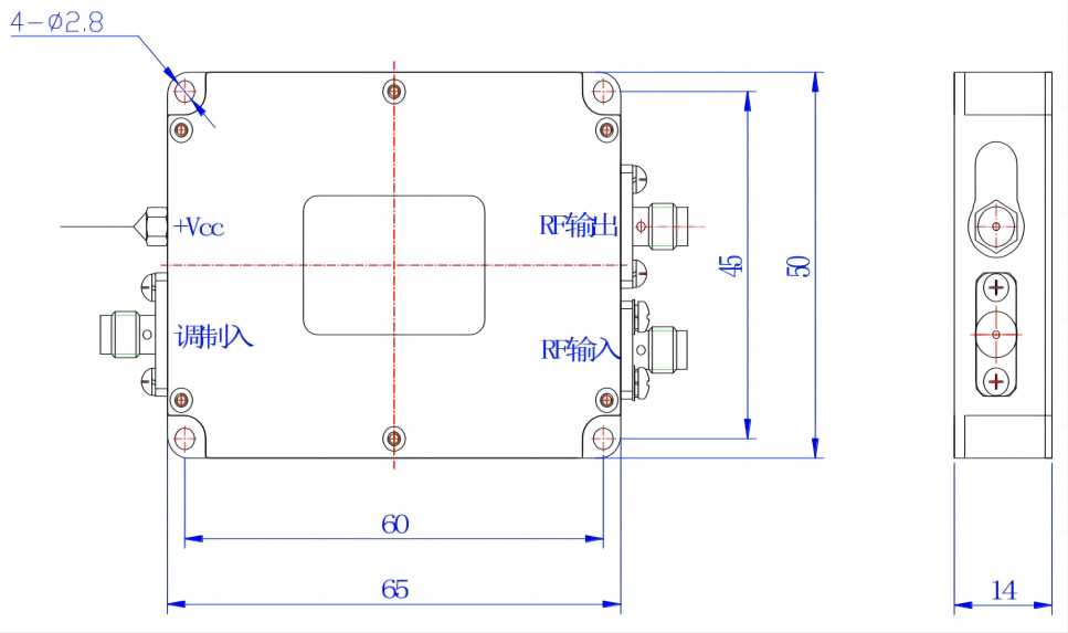
Package N
